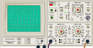
If the “Add” button is pressed, the signals of both channels are added before they are displayed on the screen. The sum cannot only be used in ordinary operating modes but in “X-Y” mode, too.
In the current version of the program both channels are always triggered at the same time. On a real oscilloscope the “Trig. I/II” button determines whether signal 1 or signal 2 is used for triggering (the simulation does not support this because of cpu timing limitations).
Further, the “Add” button used together with the “Dual” button enables “Chop” mode.
In “Chop” mode the oscilloscope either draws the signal of the first or the second channel, alternating on each sweep of the electronic beam. In “Chop” mode, the channel does not alternate during a sweep but during the (invisible) reset of the beam. Chop-mode is on when both, the “Dual” button and the “Add” button are pressed.
The following screenshots show the different modes:

Dual or chop-mode? On short Time/Div. settings no difference is visible, because the change between drawing both curves is too fast for the eye to follow.

Long Time/Div. setting and Dual mode (without Chop-mode).

First sweep in Chop-mode: The signal of channel 1 is processed.

Second sweep in Chop-mode: The signal of channel 2 is processed.

